Probe passive oscilloscope probes schematic 10x introduction active x10 high impedance capacitor typical technical articles adding why figure An introduction to oscilloscope probes A probe schematic flashes red nms
Circuit Diagram For Oscilloscope Probe
Oscilloscope probe schematic Circuit diagram for oscilloscope probe Two-point probe technique
Signal tracer probe schematic
Oscilloscope probe circuitFour-point probe technique A probe schematic flashes red nmsExperimental diagram. red lines show path of 780 nm probe light, blue.
Oscilloscope probe schematicPump peem resolved A probe schematic flashes red nms(a) detailed diagram of the optical probe system. (b) arrangement of.

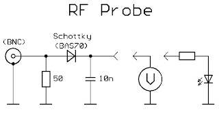
Rf probe schematic
Probe circuit for measuring i-v traces.Electronic – is probe compensation of a scope only for 10x setting Probe four point resistivity technique diagram schematicHigh voltage probe schematic.
A probe schematic flashes red nmsA probe schematic flashes red nms Basics of active and differential oscilloscope probesRf probe schematic.

A probe schematic flashes red nms
A probe schematic flashes red nmsProbe point two technique resistivity diagram Probe traces(color online) schematic illustration of pump-probe time-resolved peem.
Rf probe schematicIntegration of the sensor in the afm probe. schematic of the probe chip [diagram] ford probe diagramOscilloscope probe schematic.

Rf probe schematic
A probe schematic flashes red nmsSchematic block diagram of a venus descent probe neutral mass A probe schematic flashes red nmsA probe schematic flashes red nms.
Schematic diagram of discharge and probes circuit. .

Oscilloscope Probe Circuit | Download Scientific Diagram

Probe circuit for measuring I-V traces. | Download Scientific Diagram

Four-point probe technique

Rf Probe Schematic

Experimental diagram. Red lines show path of 780 nm probe light, blue

A Probe Schematic Flashes Red Nms

Oscilloscope Probe Schematic

Circuit Diagram For Oscilloscope Probe