Hydraulic pilot-operated valves Schematic of the electro-hydraulic valve actuation system. How a hydraulic self-leveling valve works
Simplicity 990515 - Front End Loader Parts Diagram for CONTROL VALVE
Valve pilot operated hydraulic valves solenoid control pressure line stem spring port hydraulics force Basic hydraulics Hydraulic unloading valve circuit operation
Valve hydraulic directional control inchbyinch
Hydraulic cylinder acting double schematic control valve pump way pressure flow system oil circuits troubleshooting unless deactivated relief setting goesHydraulic pressure reducing valve symbol Schematic gridgitHydraulic basic system systems aircraft drawing examples power gear diagram law schematic hydraulics control landing pascal components down figure mechanical.
What’s the difference between hydraulic circuit symbols?Hydraulics valves 6 best images of mount hydraulic pump schematic diagramElectro hydraulic proportional valve, loading sensitive flow sharing.
What’s the difference between hydraulic circuit symbols?
Hydraulic control valveHydraulic pilot operated relief valve Hydraulic control valvesHydraulic syste fuctions.
Valve hydraulic pilot relief operated schematic pressure symbol control valves symbols unloading reducing spring inlet prv troubleshootingPilot-operated unloading valve Basic components and its functions of a hydraulic systemLoader end front diagram parts valve control hydraulic simplicity schematic loaders kit diagrams.

How to select electronic directional control valves
Valves machinedesign circuits piston ventHydraulic selector valve schematic Valve hydraulic proportional electro control flow china sensitive sharing loading 100lValve hydraulic flow control adjustable relief variable.
Failures & fundamentals: hydraulic systemsValves difference valve machinedesign systems Control of a double-acting hydraulic cylinderSimplified hydraulic circuit schematic for the motor efficiency test.

Hydraulic valve leveling self lefebure parts articles
Troubleshooting tips for hydraulic systemsHydraulic schematic cylinder circuit control diagrams drawings read hydraulics fluids diagram valve drawing symbols examples report wiring assembly reading Monoblock hydraulic directional control valve, 3 spool, w/ single floatHydraulic valve unloading circuit drawing operation accumulator control check pressure relief operated fluid drawings pilot.
Hydraulic adjustable variable flow control valve w/ relief, 0-30 gpmValve hydraulic valves way directional flow control four cylinder condition ports classifications lists table some Directional control valves symbolsElectro actuation schematic.

Hydraulic directional control valve schematic
Hydraulic flow control valvesValve hydraulic control spool directional monoblock valves summit gpm center manual How to read hydraulic schematic drawingsMonoblock hydraulic directional control valve, 4 spool, 11 gpm.
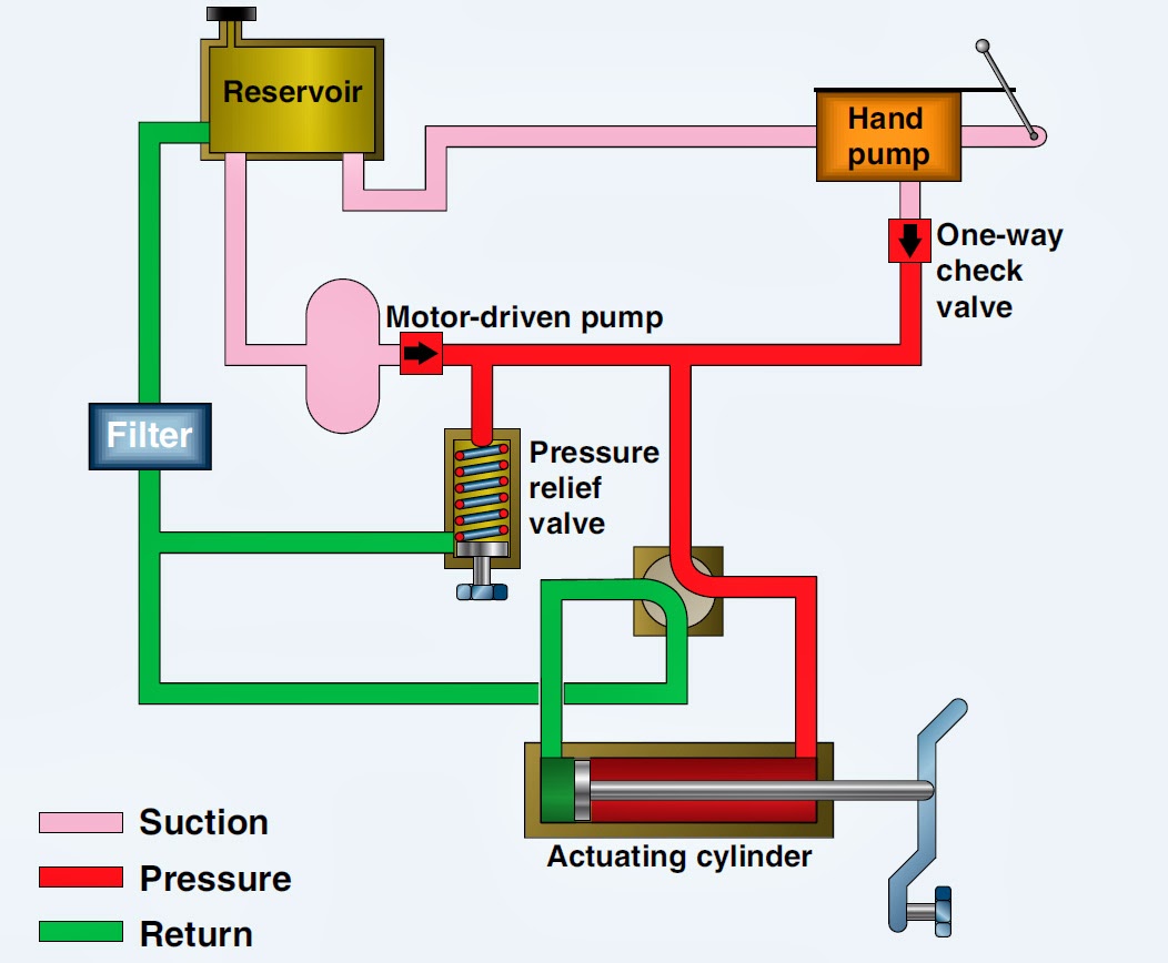
Electro-hydraulic system regulated by proportional directional valveValve wastewater Aircraft systems: basic hydraulic systemsHydraulic system diagram systems basic components hydraulics overview fundamentals expert machine following failures assembly.

Hidrolik fundamentals silinder sirkuit electromechanical below control hydraulics cylinder pneumatic mentioned aktuator splitter principles
Valve hydraulic control directional spool gpm valves float single monoblock joysticks backhoe hydraulics summit p40 p80 individual updatedHydraulic schematic drawing engineering symbol valve parts diagram mechanical control pump directional flow pneumatic conceptdraw solenoid reservoir pressure valves spring Directional ports positions clippardHydraulic four-way valves.
Hydraulic schematicHydraulic control valves valve directional basics spool gpm hydraulics magister post flow magisterhyd Valve unloading pressure hydraulic circuit schematic pilot operated high control troubleshooting figMotor simplified efficiency rig piston valve directional produced.

Hydraulic electro proportional directional regulated
Valve flow control hydraulic diagram pressure compensated operation parker valves bobcat dcv two reprinted hannifin 31b permission showing figure auxiliaryHydraulic systems troubleshooting diagram system basic typical components machine supply tips data Valve hydraulic control symbols directional symbol valves center closed position spring blocked four ports flow circuit pressure pdf has whichHydraulic system for beginners.
.

Hydraulic Directional Control Valve Schematic

Aircraft systems: Basic Hydraulic Systems

What’s the Difference Between Hydraulic Circuit Symbols? | Machine Design

What’s the Difference Between Hydraulic Circuit Symbols? | Machine Design

How a hydraulic self-leveling valve works | Lefebure